
How to Scope a 120/240V Split-Phase Home Battery Project
Date: 2026-09-27 Categories: Blog Hits: 185
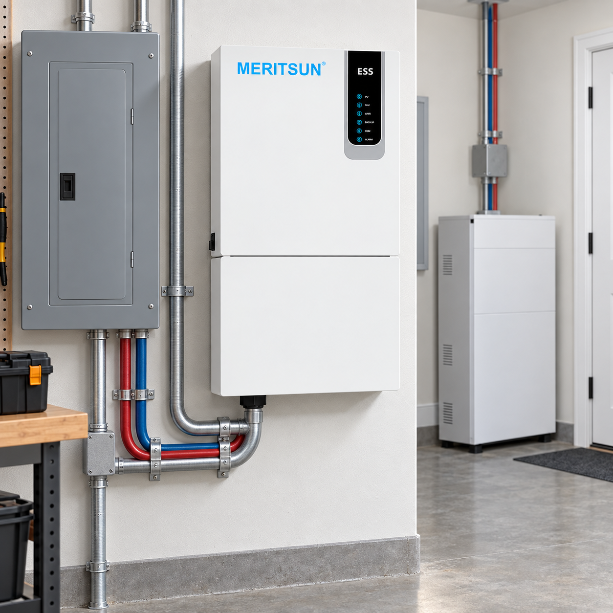
A 120/240V split-phase home battery project cannot be sized from battery kWh alone. The installer must verify that the inverter architecture can supply the required 120V and 240V loads, that L1 and L2 demand stays within the equipment’s per-leg and total output limits, and that the battery can provide the required DC current. The transfer equipment, backed-up panel, utility interconnection and local approval path must be defined before the quote is treated as final.
“Split-phase compatible” is a starting point, not a complete system design. Two projects can use the same battery capacity and still require different inverters, panels, transfer equipment and load controls because their service equipment and load profiles are different.
What is 120/240V split-phase electrical service?
Most North American homes receive a single-phase service with a center-tapped transformer secondary. The two ungrounded conductors, commonly called L1 and L2, each provide approximately 120V to neutral. Loads connected across L1 and L2 receive approximately 240V.
This is not the same as a two-phase system. In practical residential design:
- lighting and receptacle circuits are typically 120V line-to-neutral loads;
- larger equipment such as central air conditioners, water heaters, ranges, dryers and pumps may use 240V line-to-line power;
- the load on L1 and L2 is not always equal;
- some equipment requires a neutral while other 240V loads do not.
A backup system must reproduce the service conditions required by the selected circuits. The installer should confirm voltage, frequency, grounding, neutral treatment and transfer behavior using the approved equipment documentation and local requirements.
Battery capacity and inverter output answer different questions
Battery energy is measured in kilowatt-hours. Inverter output is measured in kilowatts or volt-amperes. One estimates how much energy is stored; the other limits how much power can be delivered at one time.
| Design question | Primary value to review |
|---|---|
| How long can selected loads operate? | Usable battery energy in kWh |
| Can the system run the loads at the same time? | Continuous inverter output in kW/VA |
| Can motors and compressors start? | Surge capability and duration |
| Can both legs be supported? | Split-phase output architecture and per-leg limits |
| Can the battery supply the inverter at full output? | Battery voltage, current limit, BMS and cable/protection design |
Adding batteries may extend runtime or increase available DC current when the system permits parallel operation. It does not automatically increase inverter AC output. Likewise, installing a larger inverter does not create more stored energy.
Why L1/L2 load balance matters
The main service rating does not show how backup demand is distributed. A home may have modest total consumption while one leg carries a large combination of kitchen, office or bedroom circuits.
The installer should build a circuit-level schedule that identifies:
- L1 or L2 assignment for every 120V circuit;
- all 240V circuits connected across both legs;
- continuous demand;
- intermittent demand and duty cycle;
- motor or compressor starting requirements;
- loads that can be shed, delayed or moved;
- loads that must remain available during an outage.
Some inverter systems specify a total output rating plus a maximum imbalance or per-leg limit. Others use different architectures. If the documentation does not state the permitted imbalance, do not infer it from the headline kW value.
A practical example
Assume the backed-up circuits total 5 kW at one moment. If 4.2 kW is on L1 and 0.8 kW is on L2, the total alone does not prove that the inverter can support the condition. The installer still needs the manufacturer’s per-leg or imbalance limit and the expected starting demand on L1.
This is why a photograph of the main panel is useful but insufficient. The circuit schedule and measured or estimated operating demand provide the information needed to evaluate the design.
Whole-home backup vs. a critical-loads panel
| Architecture | Best suited to | Main advantage | Main design risk |
|---|---|---|---|
| Whole-home backup | Homes with a validated load-management strategy and adequate inverter capacity | More circuits remain available | Uncontrolled simultaneous loads can exceed power limits |
| Critical-loads subpanel | Projects with a defined set of essential circuits | Clearer power boundary and predictable operation | Homeowner may expect circuits outside the panel to operate |
| Whole-home with automatic load control | Homes with several high-power loads that can be prioritized or shed | More flexible use of limited inverter power | Controls, communications and fallback behavior must be commissioned |
The correct choice is not determined by home size alone. It depends on the owner’s expectations, the high-power loads, the available inverter architecture, the transfer equipment and the service arrangement.
An honest proposal should state whether “whole-home” means every circuit is energized, every load can run simultaneously, or selected high-demand equipment will be managed. Those statements are not interchangeable.
How to evaluate 240V motors and high-demand loads
Air conditioners, well pumps, pool pumps and other motor loads can draw substantially more power during starting than during normal operation. The nameplate running current is therefore only one input.
For each priority motor load, collect:
- voltage and phase;
- rated current or running watts;
- locked-rotor current, starting current or manufacturer data;
- starting method, including any approved soft starter or variable-frequency drive;
- expected duty cycle;
- whether another large load may start at the same time;
- restart behavior after transfer to backup power.
Do not assume that an inverter’s short surge rating is sufficient simply because it exceeds the motor’s calculated start power. The surge duration, voltage stability, system impedance, battery current limit and equipment controls all matter.
Battery-to-inverter compatibility checks
A split-phase inverter still needs a battery that is electrically and operationally compatible. Before quoting the pair, verify:
- nominal battery voltage and allowed operating range;
- maximum continuous and peak charge/discharge current;
- required number of battery modules;
- approved parallel configuration and master/slave arrangement;
- BMS-to-inverter communication protocol and firmware versions;
- open-loop fallback settings, if supported;
- inverter low-voltage cutoff and battery protection coordination;
- DC overcurrent protection, conductor sizing and disconnect requirements;
- charge power from PV, grid and generator sources;
- required certifications and documentation for the destination market.
A compatibility statement should identify the exact battery and inverter models, not only the brands. A communication cable that physically fits does not prove that the protocol, firmware and operating limits are matched.
Eight steps from site survey to quote
Step 1: Identify the service topology
Record the country, utility, service voltage, main service rating, meter arrangement and whether the project is grid-connected, hybrid or off-grid.
Step 2: Document the service equipment
Capture the main panel, bus rating, main breaker, subpanels, available spaces, existing PV breakers, generator equipment and any service-rated transfer device.
Step 3: Build the circuit and load schedule
Map 120V circuits to L1 or L2 and list 240V circuits separately. Record continuous load, expected simultaneous operation and starting demand.
Step 4: Define the backup boundary
Agree on whole-home, selected-load or load-controlled backup. Mark every excluded circuit so the proposal and homeowner expectation match.
Step 5: Select the inverter architecture
Verify native split-phase output or the manufacturer-approved method for creating it. Do not combine independent single-phase inverters into a split-phase or three-phase system unless the manufacturer explicitly documents that configuration.
Step 6: Size the battery side
Calculate usable energy for the required runtime and confirm the battery bank can supply the inverter’s continuous and surge DC demand within approved limits.
Step 7: Define transfer, protection and control
Document the point of interconnection, transfer sequence, neutral and grounding arrangement, overcurrent protection, rapid shutdown where applicable, load shedding and control fallback behavior.
Step 8: Prepare the quote assumptions
State which loads are included, expected operating profile, starting SOC, minimum SOC, PV availability and design limitations. A clear assumption table reduces change orders and post-installation disputes.
Quote-stage procurement checklist
Send the battery and inverter supplier a complete project package:
- country, state/province and utility;
- 120/240V service confirmation and main-panel details;
- one-line diagram or preliminary architecture;
- critical-load and whole-home load schedules;
- L1/L2 circuit assignment;
- 240V motor and compressor data;
- PV array size, inverter type and existing solar architecture;
- proposed battery quantity and target usable energy;
- target backup duration and minimum reserve;
- generator information, if applicable;
- installation location and environmental conditions;
- permit/AHJ documentation request;
- project quantity and procurement schedule.
This information gives the supplier enough context to identify technical questions before equipment is ordered.
Commissioning and handover records
At commissioning, confirm and record:
- AC voltage from L1-to-neutral, L2-to-neutral and L1-to-L2;
- correct circuit allocation and labeling;
- normal and backup operating modes;
- transfer behavior under the approved test procedure;
- simultaneous load and controlled-load behavior;
- motor starts for approved backup loads;
- battery current, SOC limits and inverter settings;
- PV charging and grid charging, where applicable;
- alarms, communication-loss behavior and load-control fallback;
- firmware versions, photographs and exported settings.
The handover package should explain which circuits are backed up, which loads are automatically controlled and what the homeowner should do if demand exceeds the system limit.
Frequently asked questions
Is split phase the same as two-phase power?
No. North American 120/240V residential service is generally a single-phase, center-tapped system. L1 and L2 provide 120V to neutral and approximately 240V line to line.
Can a standard single-phase inverter power a 120/240V home?
Only if the inverter and system architecture are specifically designed and approved for the required 120/240V output. A 120V-only or 230V-only inverter is not automatically suitable.
Can two independent inverters be treated as one split-phase system?
Not unless the manufacturer documents synchronized split-phase operation, required wiring, controls, firmware and protection. Independent outputs must not be combined based on an installer assumption.
How should 240V air conditioners and pumps be evaluated?
Review running current, starting demand, start duration, voltage, control behavior and simultaneous loads. Confirm the inverter and battery can support the complete start event, not only the steady-state watts.
Does more battery capacity increase inverter output?
Not automatically. More battery capacity can extend runtime and may support more DC current if the design allows it. AC output remains limited by the inverter system and its configuration.
When is a critical-loads panel preferable?
It is often useful when the project has a limited inverter power budget or several nonessential high-demand circuits. It creates a clear backup boundary, but the backed-up and excluded circuits must be explained to the homeowner.
What happens if L1 and L2 are heavily unbalanced?
One leg may reach its permitted limit before total inverter output is reached. The result can be overload, load shedding or shutdown depending on the equipment. Use the manufacturer’s imbalance limits and a circuit-level load schedule.
What information should be sent with an RFQ?
At minimum, send the market, service voltage, main panel, one-line diagram, load schedule, 240V motor data, PV system, inverter model, desired battery energy, backup duration, installation location and procurement timing.
Key takeaways
- Split-phase compatibility is an architecture requirement, not a marketing label.
- Battery kWh determines energy; inverter and per-leg limits determine simultaneous power.
- L1/L2 load balance and 240V starting loads must be evaluated before the quote is finalized.
- Whole-home backup requires defined load-management rules and honest customer expectations.
- Exact battery/inverter models, firmware and documentation must be checked as a system.
Request a MERITSUN split-phase project review
MERITSUN supplies LiFePO4 battery solutions for residential, off-grid, commercial and industrial energy-storage applications and works with B2B partners on battery-system configuration. To start a project review, send the country/state, service topology, main-panel details, backed-up load schedule, 240V loads, PV capacity, inverter model, proposed battery capacity, target runtime, project quantity and procurement schedule through the MERITSUN inquiry page.
MERITSUN can review battery-side documentation and interface questions for the proposed equipment combination. The final electrical design, code compliance, utility interconnection and installation approval remain the responsibility of the licensed project parties and applicable authorities.
Sources and further reading
- Schneider Electric, Home Energy Management System Planning Guide, Version 2.0, July 24, 2025. https://www.se.com/us/en/download/document/TME13782/
- Schneider Electric Solar, XW Pro 120/240V reference configurations. https://solar.se.com/au/en/quick-reference-design-guide/
- UL Solutions, residential energy-storage system marking and installation overview. https://www.ul.com/news/qa-marking-energy-storage-systems-residential-use
- MERITSUN product portfolio. https://www.meritsunpower.com/products