
60 kWh Farm Battery Storage in the U.S.: What This 12-Module Project Shows
Date: 2026-08-01 Categories: Blog Hits: 322
A farm battery system cannot be evaluated by capacity alone. Stored energy determines how long selected loads may operate, but the inverter, battery current, motor-starting demand and load-control strategy determine whether those loads can operate at all.
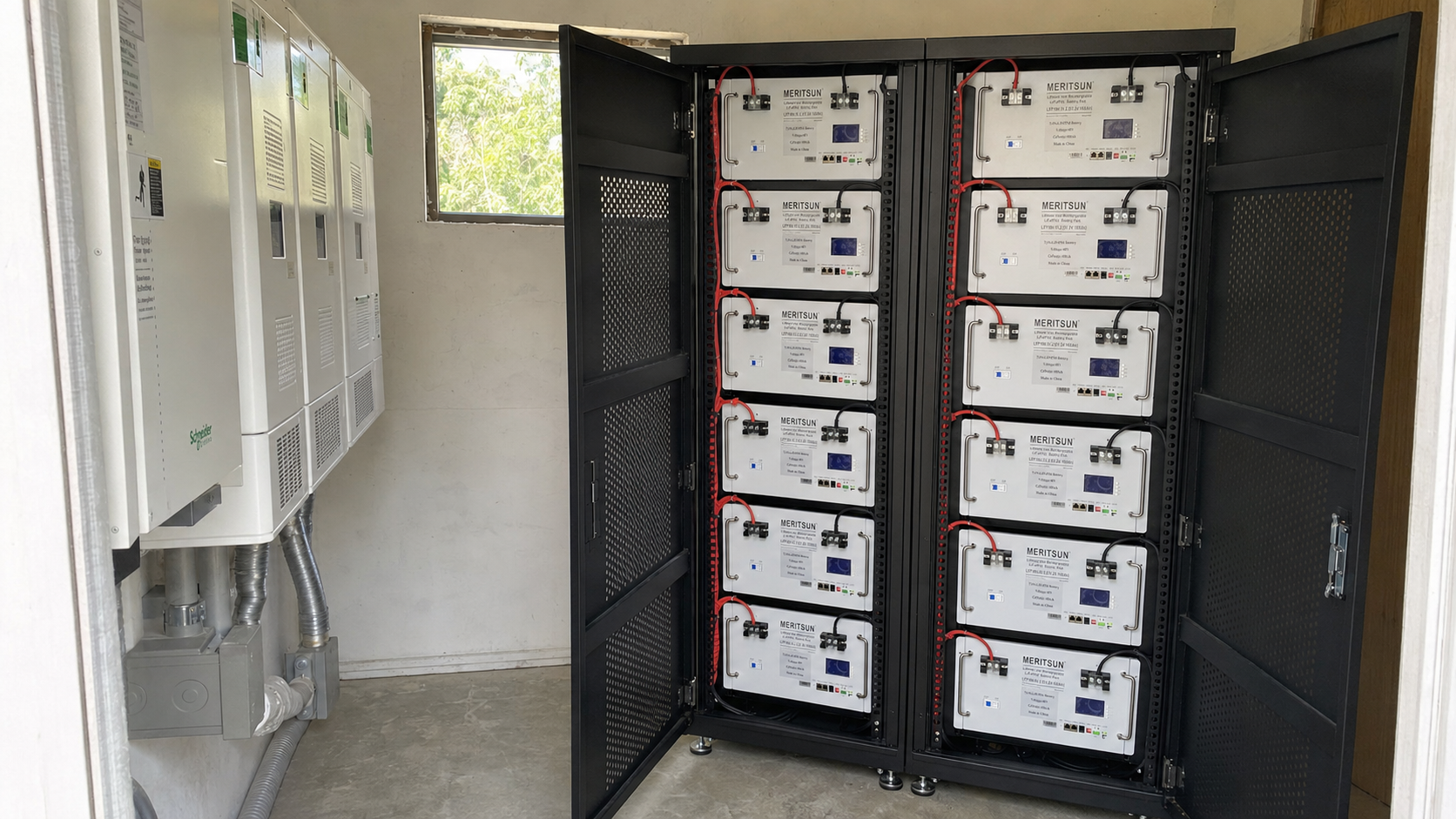
MERITSUN's U.S. farm project provides a useful example. The published project record identifies twelve 5 kWh-class battery modules connected in parallel with a Schneider inverter, creating a stated 60 kWh battery configuration for farm backup.
The most important feature of the project is not the rounded capacity figure. It is the use of twelve low-voltage modules as one parallel battery bank. That architecture offers modular capacity, but it also places specific demands on DC distribution, current sharing, inverter integration and commissioning.

Project Configuration
| Item | Published project information |
|---|---|
| Market | United States |
| Application | Solar-commercial farm backup |
| Battery model in project record | ES100-48 |
| Battery quantity | 12 modules |
| Published module capacity | 5 kWh-class |
| Connection | Parallel |
| Published system capacity | 60 kWh |
| Inverter brand | Schneider |
The project record does not publish the farm's critical loads, PV capacity, Schneider inverter model, usable battery energy or measured runtime. Those values should not be reconstructed as project results.
Why a Farm May Need Both Energy Capacity and High Starting Power
Agricultural loads are not uniform. Controls, communications and lighting may draw relatively stable power, while pumps, compressors, refrigeration and ventilation equipment can impose short, high starting demand.
This creates two separate design questions:
Energy: How many kilowatt-hours are required to operate the selected loads for the target period?
Power: How many kilowatts must the battery and inverter deliver continuously and during equipment startup?
A 60 kWh battery bank may contain enough energy for several hours of critical-load operation, yet still be unable to start a specific motor if the inverter surge capability or DC current path is insufficient. Increasing battery capacity does not automatically correct a power limitation.
For a farm project, the correct starting point is therefore a critical-load schedule that records running power, starting demand, duty cycle and required operating time. Total monthly consumption is useful for energy planning, but it does not describe outage operation.
The Central Design Choice: Twelve Modules in Parallel
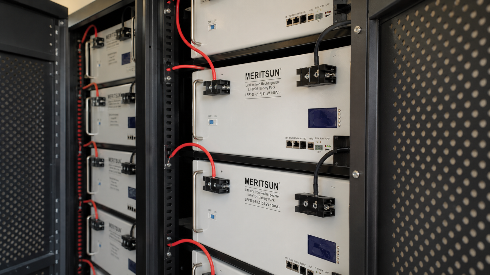
The installation image shows rack-mounted MERITSUN modules installed inside ventilated metal cabinets. The visible module marking identifies a 51.2 V, 100 Ah-class unit.
At that rating, each module contains 5.12 kWh of nominal energy:
51.2 V × 100 Ah = 5.12 kWh
Twelve modules would provide:
5.12 kWh × 12 = 61.44 kWh nominal
This is consistent with the project's rounded 5 kWh-per-module and 60 kWh system description. However, the difference between the ES100-48 name used on the project page and the LFP100-51.2 marking visible in the photograph should be confirmed against the as-built equipment list before publication as a detailed technical specification.
With twelve 100 Ah modules connected in parallel, the bank reaches approximately 1,200 Ah while remaining at the module-level voltage. This is a large-capacity, low-voltage DC architecture.
Why DC Current Matters More Than the 60 kWh Headline
At low battery voltage, power requires substantial current. Using 51.2 V as the nominal calculation basis:
| Inverter output | Ideal battery-side current | Ideal current per module |
|---|---|---|
| 5 kW | 98 A | 8.1 A |
| 10 kW | 195 A | 16.3 A |
| 15 kW | 293 A | 24.4 A |
| 20 kW | 391 A | 32.6 A |
These values exclude inverter losses and voltage variation, so actual current would be higher.
The table explains why this project must be considered as more than twelve batteries in a rack. Depending on the inverter power, the common DC path may need to carry several hundred amperes. Cable size, busbar rating, disconnects, overcurrent protection and terminal quality directly affect voltage drop, temperature and system reliability.
The exact Schneider inverter model is therefore a critical missing project detail. The brand alone does not reveal the continuous output, surge capability, battery-current limit or supported communication protocol.
Current Sharing Is the Main Parallel-System Installation Issue
Parallel batteries divide current according to the resistance of their electrical paths. Small differences in branch-cable length, conductor size, fuse resistance, connector condition or terminal torque can cause one module to contribute more current than another.
The system may continue operating even when current distribution is uneven. The problem may instead appear gradually as:
different module temperatures;
uneven state-of-charge movement;
one module reaching a voltage or current limit earlier;
repeated imbalance or protection events;
part of the installed capacity being used more heavily than the rest.
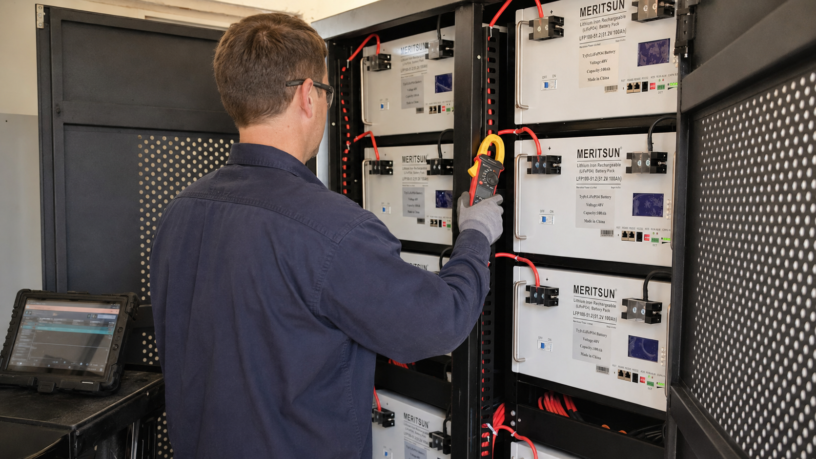
For a twelve-module bank, a meaningful commissioning test should compare total DC current with available branch- or module-level current, voltage, SOC and temperature data under a controlled load.
At a total discharge current of 200 A, ideal sharing would be approximately 16.7 A per module. Exact equality is not expected, but persistent deviation identifies a branch that requires inspection. Possible causes include cable resistance, terminal condition, branch protection, bus position, module SOC or communication status.
This type of measurement provides stronger installation evidence than a photograph showing that all twelve displays are powered.
What the Installation Image Confirms
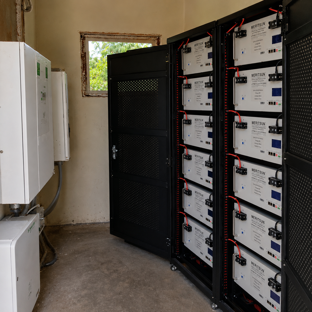
The published image shows:
MERITSUN-branded rack battery modules;
metal cabinets with perforated doors;
individual module switching or isolation;
front-access DC terminals;
local displays;
visible communication interfaces;
organized module-level cable routing.
These details support the description of a modular rack installation. The image does not show the complete busbar arrangement, main DC protection, grounding, inverter, PV system or farm distribution panel.
Those missing elements should not be described as if they were visible. A technically credible case separates what the installation image confirms from what would require the single-line diagram and commissioning record.
Schneider Inverter Integration Defines the System's Power Capability
The battery bank supplies stored energy, but the Schneider inverter determines how that energy is converted and delivered to the farm's AC loads.
A complete compatibility review would require:
exact inverter model and firmware;
permitted battery-voltage range;
continuous charge and discharge current;
continuous AC output and surge capability;
battery communication method;
open-loop or closed-loop operating mode;
SOC and low-voltage control settings;
response to loss of communication;
backup transfer and restart behavior;
generator interaction, if applicable.
This matters particularly for motor loads. If the inverter cannot support a pump or compressor starting event, additional battery kWh will not solve the problem. If the inverter supports the surge but the DC path produces excessive voltage drop, the result may still be a protective shutdown.
The battery, DC distribution, inverter and critical loads must therefore be tested as one system.
How Backup Runtime Should Be Interpreted
The stated 60 kWh capacity is not the same as usable AC energy. Runtime depends on the permitted SOC window, inverter efficiency, reserve setting, temperature, load behavior and PV generation during an outage.
An illustrative calculation can show the relationship without presenting it as a project result.
Using 61.44 kWh of mathematical nominal energy, an 80% usable window and 94% battery-to-AC efficiency:
61.44 kWh × 0.80 × 0.94 = approximately 46.2 kWh delivered to AC loads
| Average supported load | Illustrative runtime |
|---|---|
| 5 kW | 9.2 hours |
| 10 kW | 4.6 hours |
| 15 kW | 3.1 hours |
| 20 kW | 2.3 hours |
These are sizing examples, not measured results from the U.S. project.
The calculation also shows why load segmentation matters. Reserving battery energy for essential controls and selected equipment can produce a more useful backup system than attempting to operate every farm circuit without priority.
What Similar Farm Projects Can Learn From This Installation
This project offers three practical lessons for installers and EPCs.
1. Define the backup boundary before selecting capacity
Identify which loads must operate, which can be scheduled and which can remain offline. Record both running power and starting demand.
2. Treat twelve parallel modules as one engineered DC system
The project needs an approved bus topology, branch protection, cable schedule, torque record, communication plan and current-sharing test.
3. Match battery energy to inverter power and operating strategy
Battery kWh, inverter kW, usable SOC and the load sequence must be reviewed together. None of these values can define the project independently.
Information Needed for a Comparable Farm Project
Before recommending a battery configuration, the project team should provide:
country, state and utility area;
critical-load schedule;
continuous and starting power;
target backup duration;
PV array and existing inverter information;
generator details, if applicable;
proposed installation environment;
applicable electrical and permitting requirements;
communication and monitoring requirements;
expected project quantity and schedule.
Frequently Asked Questions
What is the configuration of the MERITSUN U.S. farm project?
The public project record identifies twelve 5 kWh-class battery modules connected in parallel with a Schneider inverter, providing a stated 60 kWh farm-backup configuration.
Why are twelve battery modules connected in parallel?
Parallel connection increases total amp-hour and energy capacity while maintaining the voltage of one module. It also requires controlled current sharing, branch protection and system-level BMS coordination.
Is the system exactly 60 kWh or 61.44 kWh?
The project page uses a rounded 60 kWh description. A 51.2 V, 100 Ah module contains 5.12 kWh, making twelve modules 61.44 kWh mathematically. The approved as-built equipment list should determine the final technical wording.
How much DC current can a low-voltage farm battery system carry?
Current depends on inverter power and operating voltage. At 51.2 V, a 15 kW output represents about 293 A before losses; a 20 kW output represents about 391 A. Actual current is higher after accounting for losses and voltage variation.
Can this battery system operate farm pumps or compressors?
The published information is not sufficient to confirm that. The exact Schneider inverter, motor starting demand, duty cycle, DC-voltage response and approved load sequence must be evaluated.
How long can a 60 kWh farm battery provide backup?
Runtime depends on usable battery energy and average critical load. SOC reserve, inverter efficiency, PV production, temperature and motor duty cycle also affect the result.
What is the most important commissioning test for twelve parallel modules?
A controlled load test that compares module current, voltage, SOC and temperature is essential for identifying uneven current sharing and branch resistance problems.
Can this configuration be copied for another farm?
It can be used as a project reference, but final capacity, inverter power and protection must be recalculated from the new site's loads, architecture, environmental conditions and local requirements.
Key Takeaways
The MERITSUN project uses twelve parallel battery modules for a stated 60 kWh U.S. farm-backup application.
The installation image indicates a 51.2 V, 100 Ah-class modular architecture.
Twelve modules create approximately 1,200 Ah at low voltage, making DC current and distribution central design issues.
Current sharing, protection and connection quality determine whether the installed capacity is used evenly.
The exact Schneider inverter model is needed to establish real output and motor-starting capability.
Backup runtime must be calculated from usable energy and the critical-load schedule, not from nominal capacity alone.
Similar projects require site-specific load, inverter, PV, generator and code information.
Discuss a Farm Battery Storage Project With MERITSUN
Send MERITSUN the project location, critical-load schedule, continuous and starting power, required backup time, PV capacity, generator information, inverter model and project timeline.
This information allows the battery configuration, inverter power and operating strategy to be reviewed as one system.